
はじめに
このブログでは、Meshに沿ってスキャンしているようなエフェクトが必要となったので、走査線を表示するシェーダーとMeshに沿うように表示される機能を作成方法を紹介します。
またこのスキャンエフェクト表示はMetaQuestコントローラーを使ってVRでも動作可能な形にしています。
シェーダー編
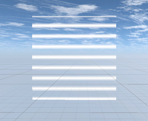
シェーダーは走査線が一定間隔で発生して、下から上に走査線が走り、それ以外の部分は透明になっているものを作ります。
イメージは画像の通りです。
シェーダーの作成
新規でUnlitシェーダーを作成して、以下のコードを貼り付けます。
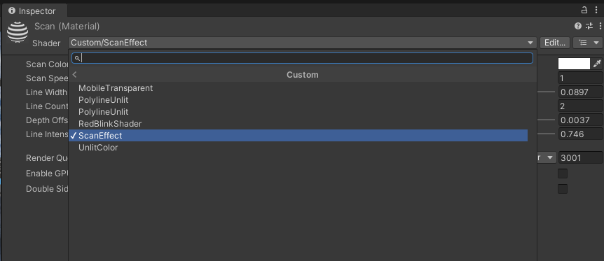
その後、新規でマテリアルを作成してシェーダーを"Custom/ScanEffect"に設定すれば完成です。
-
Shader "Custom/ScanEffect" -
{ -
Properties -
{ -
_ScanColor ("Scan Color", Color) = (1,0,0,1) // 走査線の色を赤に -
_ScanSpeed ("Scan Speed", Float) = 1.0 -
_LineWidth ("Line Width", Range(0.01, 0.2)) = 0.05 -
_LineCount ("Line Count", Float) = 3.0 -
_DepthOffset ("Depth Offset", Range(0.0001, 0.1)) = 0.01 -
_LineIntensity ("Line Intensity", Range(0.1, 2.0)) = 1.0 // 走査線の強度 -
} -
-
SubShader -
{ -
Tags { "Queue"="Transparent+1" "RenderType"="Transparent" } -
LOD 100 -
-
ZWrite Off -
ZTest LEqual -
Offset -1, -1 -
-
Blend SrcAlpha OneMinusSrcAlpha -
Cull Back -
-
Pass -
{ -
CGPROGRAM -
#pragma vertex vert -
#pragma fragment frag -
#pragma multi_compile_instancing -
-
#include "UnityCG.cginc" -
-
struct appdata -
{ -
float4 vertex : POSITION; -
float2 uv : TEXCOORD0; -
float3 normal : NORMAL; -
UNITY_VERTEX_INPUT_INSTANCE_ID -
}; -
-
struct v2f -
{ -
float2 uv : TEXCOORD0; -
float4 vertex : SV_POSITION; -
UNITY_VERTEX_OUTPUT_STEREO -
}; -
-
float4 _ScanColor; -
float _ScanSpeed; -
float _LineWidth; -
float _LineCount; -
float _DepthOffset; -
float _LineIntensity; -
-
v2f vert (appdata v) -
{ -
v2f o; -
UNITY_SETUP_INSTANCE_ID(v); -
UNITY_INITIALIZE_VERTEX_OUTPUT_STEREO(o); -
-
float3 offsetVertex = v.vertex.xyz + v.normal * _DepthOffset; -
o.vertex = UnityObjectToClipPos(float4(offsetVertex, 1)); -
o.uv = v.uv; -
return o; -
} -
-
float scanLine(float2 uv, float offset) -
{ -
float pos = frac(uv.y * _LineCount - _Time.y * _ScanSpeed + offset); -
return smoothstep(0, _LineWidth, pos) * smoothstep(_LineWidth * 2, _LineWidth, pos); -
} -
-
fixed4 frag (v2f i) : SV_Target -
{ -
UNITY_SETUP_STEREO_EYE_INDEX_POST_VERTEX(i); -
-
float scan = 0; -
for(float j = 0; j < 1; j += 0.25) -
{ -
scan += scanLine(i.uv, j); -
} -
-
// 走査線のみを表示し、背景を透明に -
float4 col = _ScanColor; -
col.a = scan * _LineIntensity; -
-
return col; -
} -
ENDCG -
} -
} -
}
シェーダーの機能解説
このシェーダーには以下の機能が含まれています。
-
スキャンラインの色 (
_ScanColor) を指定できる。 -
スキャンの速度 (
_ScanSpeed) を調整可能。 -
線の太さ (
_LineWidth) を調整可能。 -
線の本数 (
_LineCount) を設定可能。 -
深度オフセット (
_DepthOffset) により、オブジェクトの表面から少し浮かせることが可能。 -
線の強度 (
_LineIntensity) を調整可能。
これにより細かくカスタムした走査線エフェクトを表示することができます。
また仕組みとしては少しずつ位置をずらしながらscanLineを呼び出し、走査線以外は透過処理を行って走査線自体がループアニメーションになるように上に移動するものとなっています。
メッシュに沿う機能の作成
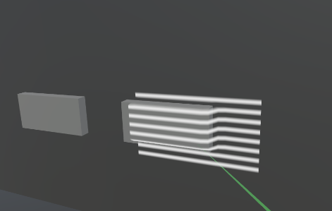
走査線のエフェクトはできたので次は壁や段差に沿うようにメッシュを変形させていきます。
MetaQuestコントローラーの先端からRayを発射し、壁などのコライダーにぶつかると、その地点を基準にメッシュが表示されるようにします。
新規でScanAreaVisualizerという名前のスクリプトを作成し、以下のコードを貼り付けてください。
-
using UnityEngine; -
[RequireComponent(typeof(MeshFilter), typeof(MeshRenderer))] -
public class ScanAreaVisualizer : MonoBehaviour -
{ -
// Fields -
[Header("Mesh Settings")] -
public float scanWidth = 1.6f; -
public float scanHeight = 0.9f; -
public int resolution = 50; // 解像度をデフォルトで上げる -
[Header("Raycast Settings")] -
public float raycastDistance = 0.5f; -
public LayerMask surfaceLayer; -
public float rayStartOffset = 0.1f; -
public int additionalRays = 2; // 追加のレイキャスト数 -
[Header("Surface Following")] -
public float maxSurfaceAngle = 85f; -
public int smoothingPasses = 1; -
public float interpolationStrength = 0.5f; // 補間の強さ -
public Material scanMaterial; -
private MeshFilter meshFilter; -
private MeshRenderer meshRenderer; -
private Vector3[] smoothedVertices; -
private Vector3 controllerPosition; -
private Quaternion controllerRotation; -
private bool controllerTransformSet = false; -
// Constants -
private readonly Vector2 NORMAL_SIZE = new Vector2(1.6f, 0.9f); // 16:9 -
private readonly Vector2 WIDE_SIZE = new Vector2(1.6f, 0.2f); // 32:9 -
public enum ScanSizePreset -
{ -
Normal, -
Wide -
} -
// Unity methods -
void Start() -
{ -
meshFilter = GetComponent<MeshFilter>(); -
meshRenderer = GetComponent<MeshRenderer>(); -
if (scanMaterial != null) -
meshRenderer.material = scanMaterial; -
smoothedVertices = new Vector3[(resolution + 1) * (resolution + 1)]; -
} -
void Update() -
{ -
// コントローラーの位置と回転が設定されていない場合は処理をスキップ -
if (!controllerTransformSet) return; -
// コントローラーの前方方向を計算 -
Vector3 rayDirection = controllerRotation * Vector3.forward; -
Vector3 rayStart = controllerPosition - rayDirection * rayStartOffset; -
if (Physics.Raycast(rayStart, rayDirection, out RaycastHit centerHit, raycastDistance, surfaceLayer)) -
{ -
if (Vector3.Angle(centerHit.normal, -rayDirection) < maxSurfaceAngle) -
{ -
// スキャンビジュアライザーの位置と回転をヒットポイントに合わせる -
transform.position = centerHit.point; -
transform.rotation = Quaternion.LookRotation(-centerHit.normal); -
UpdateMesh(centerHit.point, centerHit.normal); -
} -
else if (meshRenderer.enabled) -
{ -
meshRenderer.enabled = false; -
} -
} -
else if (meshRenderer.enabled) -
{ -
meshRenderer.enabled = false; -
} -
} -
private void OnValidate() -
{ -
raycastDistance = Mathf.Max(0.1f, raycastDistance); -
resolution = Mathf.Max(2, resolution); -
scanWidth = Mathf.Max(0.01f, scanWidth); -
scanHeight = Mathf.Max(0.01f, scanHeight); -
} -
// コントローラーの位置と回転を設定するメソッド -
public void SetControllerTransform(Vector3 position, Quaternion rotation) -
{ -
controllerPosition = position; -
controllerRotation = rotation; -
controllerTransformSet = true; -
} -
// サイズプリセットに基づいてサイズを設定 -
public void SetScanSize(ScanSizePreset preset) -
{ -
Vector2 newSize = GetSizeForPreset(preset); -
scanWidth = newSize.x; -
scanHeight = newSize.y; -
} -
// メッシュの中心を取得 -
public Vector3 GetMeshCenter() -
{ -
// ローカル座標系での中心オフセット -
Vector3 localCenterOffset = new Vector3(0f, 0f, scanHeight / 2f); // Z方向にスキャン範囲の半分をオフセット -
return transform.position + transform.rotation * localCenterOffset; -
} -
// メッシュを更新 -
private void UpdateMesh(Vector3 hitPoint, Vector3 hitNormal) -
{ -
if (!meshRenderer.enabled) -
meshRenderer.enabled = true; -
Mesh mesh = new Mesh(); -
Vector3[] vertices = new Vector3[(resolution + 1) * (resolution + 1)]; -
Vector3[] normals = new Vector3[(resolution + 1) * (resolution + 1)]; -
int[] triangles = new int[resolution * resolution * 6]; -
Vector2[] uvs = new Vector2[(resolution + 1) * (resolution + 1)]; -
float stepX = scanWidth / resolution; -
float stepY = scanHeight / resolution; -
Vector3 centerOffset = transform.right * (scanWidth / 2f) + transform.up * (scanHeight / 2f); -
Vector3 startPos = hitPoint - centerOffset; -
// マルチサンプリングのためのオフセット配列 -
Vector3[] sampleOffsets = new Vector3[additionalRays * additionalRays]; -
float offsetStep = 0.5f / additionalRays; -
for (int x = 0; x < additionalRays; x++) -
{ -
for (int y = 0; y < additionalRays; y++) -
{ -
sampleOffsets[x * additionalRays + y] = new Vector3( -
(x - additionalRays / 2f) * offsetStep * stepX, -
(y - additionalRays / 2f) * offsetStep * stepY, -
0 -
); -
} -
} -
// より精密な頂点配置 -
for (int i = 0; i <= resolution; i++) -
{ -
for (int j = 0; j <= resolution; j++) -
{ -
int index = i * (resolution + 1) + j; -
Vector3 basePos = startPos + transform.right * (j * stepX) + transform.up * (i * stepY); -
// マルチサンプリングレイキャスト -
Vector3 averagePoint = Vector3.zero; -
Vector3 averageNormal = Vector3.zero; -
int hitCount = 0; -
// メインのレイキャスト -
Vector3 rayOrigin = basePos - transform.forward * rayStartOffset; -
if (Physics.Raycast(rayOrigin, transform.forward, out RaycastHit mainHit, raycastDistance, surfaceLayer)) -
{ -
if (Vector3.Angle(mainHit.normal, -transform.forward) < maxSurfaceAngle) -
{ -
averagePoint += mainHit.point; -
averageNormal += mainHit.normal; -
hitCount++; -
} -
} -
// 追加のサンプリングレイ -
foreach (Vector3 offset in sampleOffsets) -
{ -
Vector3 sampleRayOrigin = rayOrigin + transform.TransformDirection(offset); -
if (Physics.Raycast(sampleRayOrigin, transform.forward, out RaycastHit sampleHit, raycastDistance, surfaceLayer)) -
{ -
if (Vector3.Angle(sampleHit.normal, -transform.forward) < maxSurfaceAngle) -
{ -
averagePoint += sampleHit.point; -
averageNormal += sampleHit.normal; -
hitCount++; -
} -
} -
} -
// 結果の処理 -
if (hitCount > 0) -
{ -
averagePoint /= hitCount; -
averageNormal = (averageNormal / hitCount).normalized; -
vertices[index] = transform.InverseTransformPoint(averagePoint); -
normals[index] = transform.InverseTransformDirection(averageNormal); -
} -
else -
{ -
// 補間処理の改善 -
Vector3 interpolatedPos = basePos; -
int validNeighbors = 0; -
Vector3 sumNeighbors = Vector3.zero; -
// 近傍の有効な点を探す -
if (j > 0 && vertices[index - 1] != Vector3.zero) -
{ -
sumNeighbors += transform.TransformPoint(vertices[index - 1]); -
validNeighbors++; -
} -
if (i > 0 && vertices[index - (resolution + 1)] != Vector3.zero) -
{ -
sumNeighbors += transform.TransformPoint(vertices[index - (resolution + 1)]); -
validNeighbors++; -
} -
if (validNeighbors > 0) -
{ -
interpolatedPos = Vector3.Lerp(basePos, sumNeighbors / validNeighbors, interpolationStrength); -
} -
vertices[index] = transform.InverseTransformPoint(interpolatedPos); -
normals[index] = transform.InverseTransformDirection(-transform.forward); -
} -
uvs[index] = new Vector2(j / (float)resolution, i / (float)resolution); -
} -
} -
// 改善されたスムージング処理 -
smoothedVertices = (Vector3[])vertices.Clone(); -
for (int pass = 0; pass < smoothingPasses; pass++) -
{ -
SmoothVertices(ref smoothedVertices, vertices); // オリジナルの頂点情報も渡す -
} -
// トライアングルの設定 -
int tris = 0; -
for (int i = 0; i < resolution; i++) -
{ -
for (int j = 0; j < resolution; j++) -
{ -
int vertIndex = i * (resolution + 1) + j; -
triangles[tris] = vertIndex; -
triangles[tris + 1] = vertIndex + resolution + 1; -
triangles[tris + 2] = vertIndex + 1; -
triangles[tris + 3] = vertIndex + 1; -
triangles[tris + 4] = vertIndex + resolution + 1; -
triangles[tris + 5] = vertIndex + resolution + 2; -
tris += 6; -
} -
} -
mesh.vertices = smoothedVertices; -
mesh.triangles = triangles; -
mesh.normals = normals; -
mesh.uv = uvs; -
meshFilter.mesh = mesh; -
} -
// 頂点同士のスムーズ化 -
private void SmoothVertices(ref Vector3[] vertices, Vector3[] originalVertices) -
{ -
Vector3[] tempVertices = (Vector3[])vertices.Clone(); -
for (int i = 1; i < resolution; i++) -
{ -
for (int j = 1; j < resolution; j++) -
{ -
int index = i * (resolution + 1) + j; -
Vector3 average = vertices[index] * 2.0f + -
vertices[index - 1] + -
vertices[index + 1] + -
vertices[index - (resolution + 1)] + -
vertices[index + (resolution + 1)]; -
// オリジナルの頂点位置も考慮 -
tempVertices[index] = Vector3.Lerp(average / 6f, originalVertices[index], 0.3f); -
} -
} -
vertices = tempVertices; -
} -
// プリセットに応じたサイズを返す -
private Vector2 GetSizeForPreset(ScanSizePreset preset) -
{ -
return preset switch -
{ -
ScanSizePreset.Wide => WIDE_SIZE, -
_ => NORMAL_SIZE, -
}; -
} -
public bool IsDisplaying -
{ -
get -
{ -
return meshRenderer != null && meshRenderer.enabled; -
} -
} -
}
上記のコードを適当なGameObjectにアタッチして、スキャンエフェクトの影響を受けるSurface Layerとマテリアルの設定(最初に作った走査線のマテリアル)を行えばエフェクト部分は完了です。
後はこれを別のスクリプトから位置と回転情報を受け取れば完成です。
メッシュ変形の機能解説
メッシュ変形で用意されている調整可能な機能は以下の通りです。
[]
-
scanWidth/scanHeight→ スキャン範囲のサイズ -
resolution→ メッシュの解像度(頂点の密度)
[]
-
raycastDistance→ レイキャストの最大距離(表面との距離) -
surfaceLayer→ どのレイヤーに対してレイキャストを行うか -
rayStartOffset→ レイキャストの開始位置 -
additionalRays→ 補助レイキャストの数(補間用)
-
public Material scanMaterial → スキャン時のマテリアル(
ScanEffect.shaderなどを適用するため)
-
meshFilter/meshRenderer→MeshFilterとMeshRendererを取得し、スキャンメッシュを管理する -
smoothedVertices→ スムージング後の頂点データ -
controllerPosition/controllerRotation→ コントローラーの位置と回転情報 -
controllerTransformSet→ コントローラーの位置・回転が設定されたかどうか
仕組みは以下のようになります。
初めにMeshFilterとMeshRendererを取得してマテリアルを適用します。
次に毎フレーム、コントローラーの向きにレイを飛ばし、オブジェクトの表面にヒットするか確認、表面の角度が maxSurfaceAngle以内ならスキャンエリアの位置と回転を調整してUpdateMesh()
を呼び出してメッシュを再計算します。レイがヒットしなかったらmeshRendererを無効化します。
UpdateMesh()ではmeshRenderer を有効化し、頂点などを初期化した後にスキャン範囲を resolution に応じたグリッドで生成します。
そしてメッシュの形に違和感がないようにSmoothVerticesでメッシュのスムージングを行います。
コントローラーから位置と回転情報を送ってもらう
最後にコントローラーの位置と回転情報が取れたら正常に動きます。
データを渡す処理は以下の通りです。
- using UnityEngine;
- public class ControllerManager : MonoBehaviour
- {
- public ScanAreaVisualizer scanVisualizer;
- public GameObject VRcontroller;
- void Update()
- {
- // VRコントローラーの位置と回転を取得
- Transform controller = VRcontroller.transform;
- // コントローラーの位置と回転をScanAreaVisualizerに設定
- scanVisualizer.SetControllerTransform(controller.position, controller.rotation);
- }
- }
上記のコードを適当なGameObjectに設定して、ScanVisualizerとコントローラーのアタッチを行うと、スキャンエフェクトが表示されます。
まとめ
走査線のエフェクトをシェーダーで作成、またメッシュも壁なや物などの形状に合わせて変形する機能も作成できました。精度を高くすると動作が重たくなりますが、サンプルコードぐらいの設定であればスタンドアロンのMetaQuestでも快適に動作が可能です。
また、注意点として全てのオブジェクトに最初からスキャンエフェクトが作用するわけではなく、自分で設定したレイヤーのオブジェクトだけこのスキャンの影響を受けるようになります。

上記ブログの内容に少しでも興味がありましたら、お気軽にご連絡ください。
弊社のエンジニアがフレンドリーに対応させていただきます。